
Understanding and Measuring The Pull-Out and Pull-In Torque of a Stepper Motor
By definition, stepper motors are brushless motors; as such, they can provide numerous advantages over DC motors, especially for applications requiring a more cost-effective and precise positioning system. To select the right stepper motor for an application, it is critical that the design engineer both understand and account for the pull-out and pull-in torque curves of the stepper motor.
Comparing Bldc Motors With Stepper Motors
Figure 1 : shows the torque developed by a three-phase BLDC motor with six-step commutation. The feedback of the hall sensors integrated into the motor is used to keep track of the rotor position. This information allows commutation of the three phases at the right moment to maintain an angle of 90° +/- 30° between the magnetic field of the rotor and the stator.
There is a small current ripple, but the torque developed by the motor is rather stable and not significantly dependent on the rotor position. Using a high-resolution encoder for a more precise rotor position feedback would reduce the torque ripple to nearly zero.
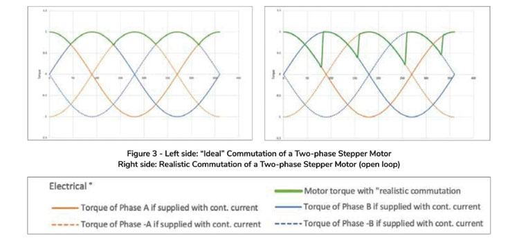
Figure 2 : shows a simple version of a stepper motor: a magnet with one pole pair serving as a rotor and two separate phases located in the stator. This design provides four full steps over one mechanical revolution. The resulting torque curves showcasing a continuous current being applied to each phase are illustrated in Figure 3 (blue and orange graphs). If the motor is driven in Full Step enabling only a single phase at a time, a current will be applied in the following order: A, B, -A, -B.
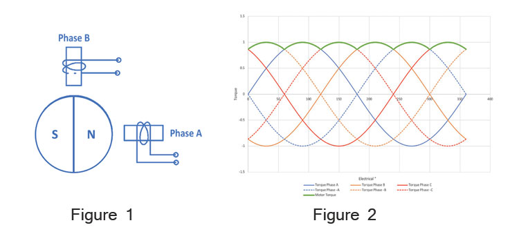
The green graphs in Figure 3 illustrate the resulting torque at the motor shaft. Unlike with a BLDC motor, the motor torque of a stepper motor will significantly depend on the rotor position. A stepper motor will typically be driven in open loop mode without rotor position feedback to achieve a cost-efficient and simple design. The commutation thus occurs with an external signal (steps per second) without knowing the current rotor position. An “ideal” commutation would enable the current in the phase when the rotor is positioned exactly between two phases. However, in open loop (i.e., without a rotor position feedback), the rotor may not always be in the ideal position. This uncertainty must be taken into account when sizing a stepper motor by applying a safety factor on the pull-out torque.
Now that we’ve covered these differences between three-phase BLDC and stepper motors, let’s look at how to understand the pull-out and pull-in torque of stepper motors.
Exploring Stepper Motor Pull-Out Torque
How Pull-Out Torque Is Measured
To better understand how the maximum pull-out torque is defined, it’s important to look at how it is measured. Typically, the pull-out torque is measured under the following conditions:
- No load on the motor
- Open loop mode
- With one specific driver
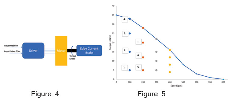
Figure 4 : showcases the measurement setup for the pull-out torque. The motor will be connected to a driver, which defines the direction of rotation, as well as the velocity of the motor by sending a pulsed signal. The motor shaft is connected to a variable brake system (e.g. an eddy current brake) which allows a variable load to be applied to the motor.
The measurement itself is conducted as follows:
- The motor is started without any load and is brought up to a given, a rather low speed of 100 pulses per second (or pps) to start.
- An increasing load is applied on the motor shaft using the brake system until the motor loses its synchronization.
- The maximum load under which the motor can rotate at 100 pps without losing synchronization is stored.
- Steps 1-3 are repeated but with a higher speed, e.g. 200 pps and so forth.
The maximum load values for each velocity measured during Step 3 represents the pull-out torque curve of the motor and is illustrated in Figure 5. Due to resonance, certain velocities can lead to erratic motion of the motor and need to be avoided, which can be shown additionally in the pull-out torque diagram.
Pull-Out Torque in Practice
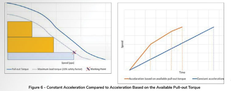
In practice, the pull-out torque curve is used to define what torque and speed range the motors can be safely driven in open loop. For the maximum load torque, a safety factor of usually 30% is considered (represented in Figure 6 by the dotted blue line), as compared to the maximum available pull-out torque (represented in Figure 6 by the solid blue line).
Furthermore, the pull-out torque is used to determine the optimal acceleration profile for the motor. In the example shown in Figure 6, the motor should achieve a working point represented by the red cross. There are two ways to accelerate the motor to the required speed:
- If only the maximum available pullout torque at the desired working point is considered, the motor accelerates linearly with a constant torque. A minimum range of the available pull-out torque is used, represented by the blue rectangle.
- A more sophisticated way is to adapt the acceleration torque based on the available pull-out torque. At low speed, a higher pull-out torque can be used to accelerate faster. This leads to a non-linear acceleration, thus reaching the desired speed faster. The entire range of the available pull-out torque is used, represented by the orange rectangles.
Exploring Stepper Motor Pull-In Torque
How Pull-in Torque is Measured
The pull-in torque can, for example, be measured with the setup illustrated in Figure 7. A disk is mounted on the motor shaft and a cord is wrapped around it. The tension forces F1 and F2 in the cord are measured, and the difference between these forces creates a load torque on the motor, which is dependent on the diameter of the disk. The resulting load on the motor shaft consists of pure friction torque with negligible load inertia. The only inertia present during the measurement will therefore be the rotor inertia of the motor. The motor is connected to a driver in open-loop mode and the entire measurement is done without an acceleration ramp.
The measurement is typically conducted as follows:
- A low load is applied on the motor.
- The driver is set to a low velocity and enabled. If the motor can start, the same step is repeated at a higher velocity.
- Once the motor is unable to start, the maximum start-up frequency for the given load has been found.
- Steps 1-3 are then repeated with a higher load.
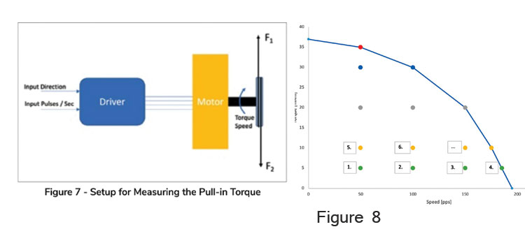
The maximum velocity values captured during Step 3 represent the pull-in torque curve shown in Figure 8. Typically, motor suppliers (including Portescap) will provide the pull-in torque curve of the unloaded motor and measure with one specific driver. In the actual application, the inertia of the load needs to be considered as well, as this additional inertia acting on the motor shaft will decrease the available pull-in torque of the motor. To summarize, the factors which influence the pull-in torque of a stepper motor are:
- The motors’ characteristics – e.g., the rotor inertia
- The inertia of the attached to the motor shaft
- The total load torque on the motor
- For more information,
Pull-In Torque In Practice
In practice, there are two key situations where the pull-in torque is used when sizing a stepper motor:
For slow motions where no acceleration of the motor is required, the motor will be started directly with the desired speed using a fixed number of steps per second.
In certain cases, the natural resonance frequency of a stepper motor can be avoided by starting it at a speed above this resonance frequency, for which the pull-in torque needs to be known.
Conclusion
When selecting the right stepper motor for an application, it is critical to understand the pull-out and pull-in torque curve of the motor. The pull-out torque curve defines the maximum torque the motor can deliver when driven at a certain speed, without losing its synchronization. Exceeding the pull-out torque will make the motor lose its synchronization, which results in erratic motion; this is why a safety factor of roughly 30% should be considered for the maximum load torque. Non-linear acceleration using the maximum available pull-out torque allows the desired speed to be reached faster, thereby optimizing the motor for applications requiring highly dynamic motion. Driving the motor in closed loop using an encoder allows one to skip the safety factor and use the maximum available pull-out torque of the motor. In this case, the motor is driven like a brushless DC.
Many motor suppliers will provide the pull-in torque curve, however, defines the maximum speed and torque under which the motor can start without an acceleration ramp. Typically, motor suppliers (including Portescap) will provide the pull-in torque curve of the motor without any load torque or inertia and measured with a specific driver. For applications with additional load inertia acting on the motor, it’s best to get in touch with the motor supplier to calculate the available pull-in torque. In certain cases, the natural resonance frequency of a stepper can be avoided by starting the motor at a speed above the resonance frequency, for which the pull-in torque needs to be known.
![]()